Control System Design
#Control System Design
See the notebook (also located in the code repo in the python/ subdirectory) here
High pass filters are extremely important to a properly functioning motion simulator. The point of adding high pass filters is evident when one considers the motion of real vehicles and compares this consideration to the possible motion of the simulator. While the motion simulator is capable of motion in six degrees of freedom (surge, sway, heave, roll, pitch, and yaw) just like a real vehicle, however the physical limits on these motions imposed by the design of the simulator mean that it is not capable of perfectly mimicking motion of the vehicle. This means the simulator must use its limited range of motion to trick the user into thinking he or she is in fact experiencing the real deal.
The physical limits of the platform are more imposing in motions directions than in others. Take surge or yaw for example. Both of these motions can theoretically be sustained by a real vehicle for an infinite amount of time. Since The platform cannot surge or yaw infinitely, a different motion must be added in order to simulate this effect. In the case of surge, the platform would be allowed to move forward linearly at the start of the motion, and then pitched backward to maintain the feeling of forward acceleration. While this is happening, the platform would need to recover from the linear motion by translating itself back toward its initial position. This must be done in such a way that it successfully tricks the driver into ignoring this reversing motion, so as to preserve the realism of the simulation. The standard approach to this problem is to employ the Classical Washout Algorithm, which uses high and low pass filters to "washout" the undesirable recovery motions of the simulator.
The first motion the design team decided to tackle was yaw. Yaw was investigated first as it is one of the most problematic motions to washout. A real vehicle can yaw infinitely, but the motion simulator is limited to a small angular range. Because of this, a natural starting point was to determine what the actual yaw limit of the platform was. This was done using a MATLAB simulation of the platform motion, available [here] (https://github.com/Alexanderallenbrown/MotionBase/blob/HighPassFilterDemos/Simulations/MaxYaw.m).
A simple 2-D state space vehicle dynamics model (the bicycle model) was used to solve for a range of potential yaw rates that could be simulated by the motion base. Using a statistical distribution of relevant vehicle parameters obtained here, the design team was able to begin simulating a 50th percentile vehicle in the motion base.
The first objective was exploring yaw rate for various vehicle speeds. Using the transfer function of the vehicle motion that was achieved through use of the bicycle model, the team was able to see the resulting platform yaw for a sinusoidal vehicle steering input, which was taken to be 5 degrees. By adding the high pass filter to this transfer function, the team was able to manipulate the filter and observe the changes it has on the platform's motion. Bode plots from this analysis are shown below:
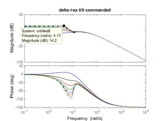
Commanded Tilt due to x Acceleration of the Platform and Error
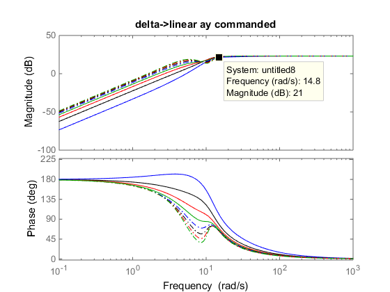
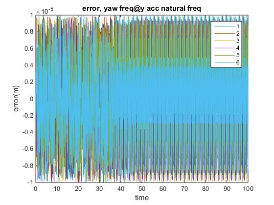
Commanded Tilt due to y Acceleration of the Platform and Error
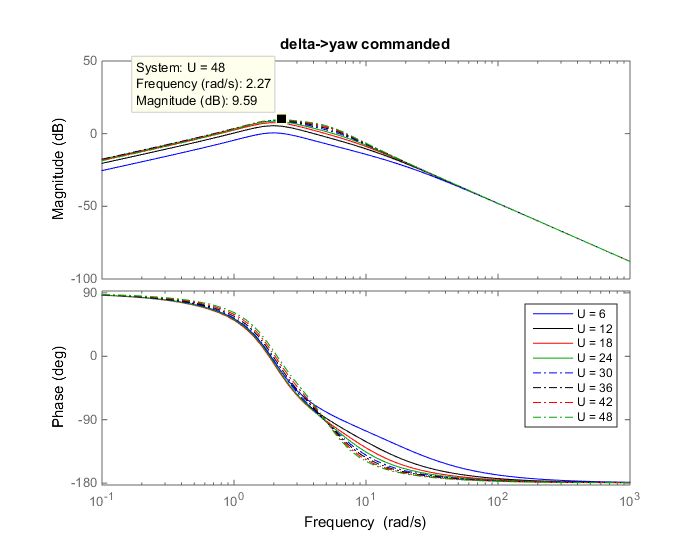 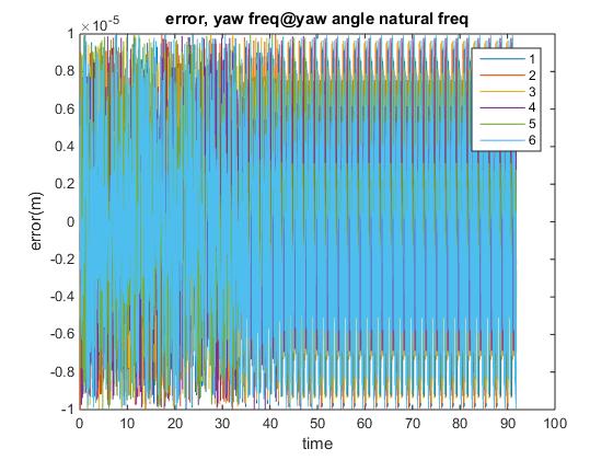

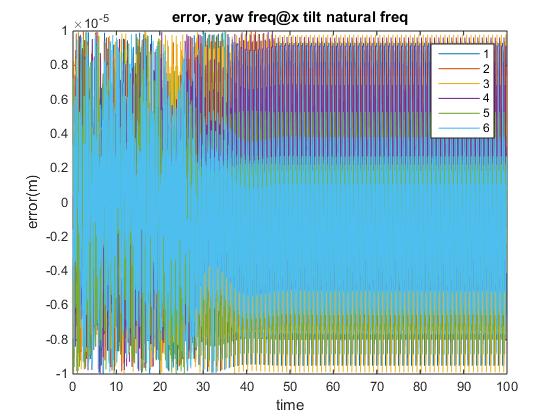
Commanded Yaw of the Platform and Error
Once the sinusoidal steering input of 5sin(wt) was input, the motion envelope that resulted was examined to see if the platform was capable of the commanded motions. The torque needed to be supplied by the motors to achieve this was also examined. Below is a block diagram of the simulation. Note that the outputs from this simulation are the result only of a simulated steering input. The structure of this block diagram can be viewed as a snippet of the block diagram for the entire system, as this is a good representation of the layout it follows.
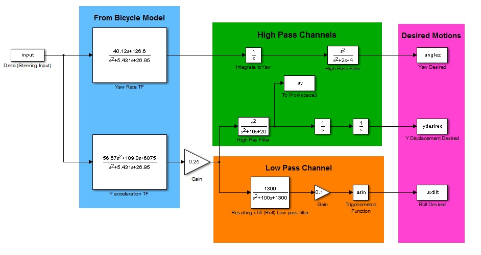
Simulink Diagram of Steering "delta" Input Simulation
Next, the maximum roll angle of the platform given the physical sizes of the CAD design [here] (https://github.com/Alexanderallenbrown/MotionBase/wiki/Mechanical-Design#second-iteration) was determined. The angle limit (about 18 degrees) is shown below, along with the angle of each motor arm which would correspond to this motion. This roll angle was deemed to be enough, meaning that the team was happy with a roll capability of about 18 degrees. Below "error" is taken to be the error in the calculated lengths of the control arms compared to the actual lengths of the control arms.
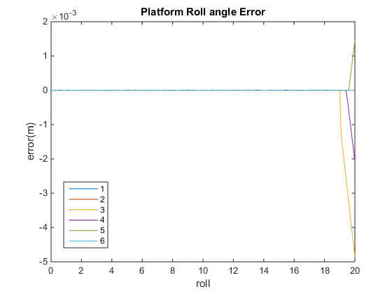
Error in the Control Arm Length vs Platform Roll Angle.
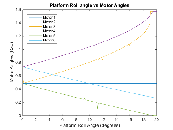
Roll Angle of the Platform vs Angle of Each Motor Arm