Recoil Analysis & Precision Trigger Observation Recorder
(a Ballistic Recoil Tracking System)
Precision shooting is one of my favorite hobbies. As is the case with most hobbies, it can be an endless journey of finding and purchasing (or building) items to continually make small forward gains – in this case - better rifles, better scopes, better ammo, tools for measuring things like bullet velocity and weather, etc. However, at the end of the day, one common factor can make the difference between success and failure – the human.
Precision shooting involves shooting at longer distances – often over 500 yards. At this distance, the common .223 bullet will drop approximately 5 feet and will see it’s velocity split in half, almost transitioning from super-sonic to sub-sonic. Factors like spin drift will see a (generally right) curve. Any small gust of wind, especially as the bullet slows, will shove the bullet far off course. Finally, in most cases, it is nearly impossible to hold a scope on a target at those distances with little to no movement – just a heartbeat will move the scope several feet or more when shooting out that far.
As such, it can be very difficult to discern equipment troubles (a troublesome batch of ammo, some piece of the rifle not set up correctly) from other factors (gusts of wind, poor trigger control). Failure to build a proper base (how the rifle and shooter are supported) can impact the amount of movement the rifle is subjected to. Incorrect trigger technique can force movement on the rifle at the most critical time in the firing sequence.
This project aims to remove some of the factors of shooting (bullet physics, environmental conditions) and isolate one particular aspect of the hobby – how steady is the shooter when the bullet goes off, and how is the rifle moving during that time. These are aspects of shooting that can be improved with practice and time – and getting a good feedback loop for improving these can be a huge help.
Some commercial examples of a system like this exist. One of the most popular is the Mantis X10 Elite Shooting Performance System – at approximately $249. This device is mainly marketed as a dry-fire tool on pistols. (using a laser cartridge indoors to practice draw and fire times as well as accuracy)
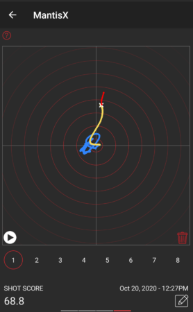
The system is very capable, but the core concept is the ability to detect and quantify movement during the time of fire in the X/Z plane (up and down, left and right). This can be used to compare different shooting platforms/techniques and can show progress over time if these things are improving.
While it would make sense from a practical “time spent” perspective to just purchase one of these devices, what fun would that be? Let’s see what kind of results can be had using some cheap off-the-shelf electronic modules and a little bit of code. A “DIY” recoil measurement system might be fun to have and build for many hobbyists.
Let’s start out with some basic requirements of a system like this:
- Microphone and IMU detection of the shot.
- Measure movement from just before the time of fire until just after the time of fire.1
- Upload data to a Bluetooth mobile app for display and multi-shot comparison.
- Battery powered – either small disposable or small rechargeable.
- 3d-printable enclosure, attachment via picatinny rail.
- High-precision– both in terms of movement accuracy and samples per second.
In addition, some nice-to-haves:
- LED indicator to show a shot was captured.
- Simple display to show preview of shot movement.
- Temperature, Barometric Pressure, Humidity measurements.
- Basic button(s) for on/off and sensitivity.
Stretch goals:
- Tilt sensor/tilt indication
- Full ballistic calculations on mobile app – enter target distance and allow the system to indicate an approximate “human shooter error” induced by movement.
My typical go-to part for small projects such as this is the AVR family of microcontrollers – small, low power and relatively high clock rate, 3.3V and 5V compatible, UPDI programmable, loads of on-board features such as UARTs, Timers, and lots of configurability for external interrupts and analog/digital readings. In addition, many of the parts in this family can be found in hand-solderable packages for easy prototyping and one-off custom PCB hand soldering. The AVR128DA32 is one of my favorites and I’ve made several projects with this device.
However, given some of the requirements of this system, there are likely some better choices available. Finding a part with built-in Bluetooth would be ideal – and something with even higher clock speeds (to measure the recoil as fast as possible) would be ideal.
After quite a bit of research, I settled on the nRF52XXX series of processors – for speed, power consumption, built-in features such as BLE, and availability. They cost a bit more than my typical AVR parts, but are far more capable – I wouldn’t need to add (and worry about) external Bluetooth radio hardware, which is a big win. It’s quite a bit faster (64MHz vs 24MHz) and is 32-bit (vs 8-bit). It also has quite a bit more ram and flash, which will be useful for buffering gyro data before it gets sent to the mobile app. It’s 3-4x more expensive than the part I typically like to use for prototypes – but the capability is more than worth it.
Most notably, this new part will require a different workflow. I find the “drop a hex file in a directory” style bootloaders to be annoying and slow. Instead, I’ll be purchasing a SEGGER J-Link EDU Mini JTAG debugger to aid in development. Not only can this be used to program the device, but setting breakpoints will be a great departure from my typical “printf debugging.”
Fortunately, with the explosion of small DIY drone development, there are many options for a gyro/accelerometer units (sometimes called an IMU or Inertial Measurement Unit).
I have some limited experience with the LSM6 series of gyro/accelerometer2 – enough to get the basic idea of how it works and understand the general amount of noise it can produce and how hard it is to work with and get long-term stable readings. Fortunately, for this project, relative movement is the most important aspect – not absolute orientation, so we can likely work around some noise. This part has an advantage in that breakout boards are readily available on amazon for a few bucks.
A much more ideal unit might be something like an ICM-42688. Lower noise, higher sample rate, similar range of measurement. Depending on the success of the LSM6, this could be an excellent future evolution. Unfortunately, this part does not come in easily hand-solderable packages, and the links on amazon for breakout boards look a bit suspect, plus weeks to months out for shipping. This could become a “when a real PCB gets designed, we add layouts for both parts and can solder one or the other on the PCB” kind of situation. Until then, a breakout module from amazon on a breadboard will do nicely.
There are many different atmospheric sensors out there3 – all fairly accurate and almost all with some sort of noise filtering/smoothing. In general, these tend to be factory calibrated (and can be re-calibrated by the end user) and as such they tend to be very close in performance to each other. While these environmental factors are important, half a degree won’t change much, and these measurements are “nice to have” anyway.
This device needs to run for an entire day of shooting, with time to spare. Ideally, this would be 8-12 hours. Indicator LEDs and OLED displays can be put to sleep after 30ish seconds and as such are not a power concern. The big X-factor is “how much BLE data will be transmitted.” It’s unclear how much power this will require, and if power spikes will result from this transmission. For now, including a small LiPo pack will be the go-to answer, but a later version with a small form factor disposable battery (a single AAA?) is definitely a desire. Alternately, a 10440 rechargable lithium cell (same size as AAA) would be a good option so charging electronics can be left out of the system, and users can supply their own spare batteries.
As I was researching some of the nRF52XXX modules available on amazon, I stumbled upon the Adafruit Feather nRF52840 Sense for $39.50
This fantastic little module is the size of two postage stamps and includes:
- 1MB Flash, 256K RAM
- BLE (Bluetooth Low Energy)
- LSM6 Series Accelerometer/Gyro
- PDM Microphone/Sound Sensor
- SHT30 and BMP280 for Temperature/Humidity/Pressure
- NeoPixel LED
- Exposed I2C/TWI lines (for future expansion)
- Exposed SWD debug ports (for JTAG programming/debugging)
- Reset and User Button
Useful Links:
- Adafruit Feather nRF5280 Sense Startup Guide
- Pinout
- Schematic
- Debug Header for Breadboard JTAG Connection
- Base nRF52XXX Feather
The IMU here isn't ideal - but would be a good starting point. Using an off-the-shelf unit like this will get the project kicked off quickly so building a custom system on a base nRF52XXX unit won't be a barrier to exploring this project.
Updating the bootloader on these parts is typically the first order of business. In my case, the part was on 0.8.0, which satisfied some of the “careful, you must be beyond this version” verbiage in the guide. That being said, a later version was available, so I upgraded. It was as simple as connecting the feather sense to USB and dropping a new UF2 file into the USB drive that appeared. The part rebooted and indicated in a local text file that it had been upgraded.
Later on, I managed to brick the feather, and wanted to run the bootloader for some reason or another. While the Adafruit page lists direct links to the latest UF2 bootloader, a hex file is necessary to reprogram the device via JTAG. A link from the Adafruit site to the github pages allowed me to find the “feather_nrf52840sense_bootloader-0.10.0” hex file easily.
I’m a huge fan of JetBrains products, and while the Arduino IDE has come a long way, it still feels purpose-built for single-file prototypes, and many of the helpful coder tools are missing. Some of their refactor tools and coding suggestions make programming more enjoyable and reduce errors. I’ve had a lot of success getting CLion to work with the AVR128DA32 projects I’ve done. However, after spending many hours trying to bend CLion and PlatformIO to my will4 and make it talk to the Feather Sense, I admitted defeat, closed CLion, and started following the actual manual for installation and development. I’m still sore about this, and don’t promise to never revisit this topic.
Installation here involved adding links to additional board managers (the Adafruit github) and installing some tools specific to the nRF52. Caution should be taken – there are several variations of the feather and not all of them are compatible with all of the samples or libraries. At the end of the day, I was able to get some simple hello-world style LED blinking light applications to work successfully. But, once again, this development environment is not super ideal.
Many years ago, I used Visual Studio (and sometimes Visual Studio Code) extensively. It wasn’t super refined, and I gradually migrated over to JetBrains products for my professional daily tasks. I haven’t really gone back, unless you count “oops windows opened visual studio by accident to inspect that CPP file.” I didn’t have super high hopes.
PlatformIO integration has really been well done. Installation was a snap. Refreshing the platformio.ini file to modify project options or add library dependencies was almost automatic.
The feather sense is supported by nordic’s nRF Connect Visual Studio plug-in. This is exposed as a “folder icon” on the left bar of the screen and is where you start new projects. This opens a wizard and sets up the basic template of your PlatformIO project, specific to the feather board you’re using.
In addition, I installed the JLink extensions, which gave me the ability to upload compiled code via JTAG and set breakpoints with only a few minor additions to the platformio.ini file.
In the past, I’ve been stalwart on my desire to “do everything myself.” I typically use AI only for stand-alone utilities where the definition of the problem and end goal is relatively simple and the implementation could be complex – purely as a time-saver/annoyance limiter.
However, during a recent deep-dive into setting timers on an AVR128DA32, I found myself 5 hours in to interrupt triggering logic not working and very annoyed. Out of frustration (or desperation, you decide) I dumped the entire 600 page PDF into ChatGPT and told it to make me C code that would give me an interrupt trigger every X milliseconds using Timer2. I had low hopes – that’s a big document and I didn’t give it many hints. To my surprise and delight, it got the task right on the first shot.
This project, both hardware and software, is a collaborative effort between human and machine. Quite a bit of time was spent a writing a TDD (technical design document) and iterating on the output of code. Sometimes the result from AI was close, other times it was the wrong architecture. It’s not a replacement for humans, yet. But it’s a fantastic tool.
Practically speaking, filling out an API (.h / header file) and asking AI to make a CPP file tends to get close enough to be good. Asking it to help debug why certain bits of hardware might not be responding is helpful - things like "here's code to reset the I2C bus" was super handy. That's how most of this project was developed.
Footnotes
-
Assuming 3000fps muzzle velocity, a bullet takes between 1 and 1.5ms to travel the length of a typical barrel used in precision shooting. However, it can take between 2.5 and 9.0 milliseconds for the trigger pull to activate ignition. We should aim for recording the previous 50ms and the following 100ms of movement. ↩
-
I tested several gyro/accelerometer units when building an underwater digital compass system – attempting to get a “level reading” is important in that application. ↩
-
A previous project involved a x16 array of various I2C temperature/humidity/pressure sensors and studied drift and variance over time. The results were insignificant in that the sensors tended to all be more than accurate enough for typical hobbyist needs. ↩
-
Many of the steps I used involved installation of nordic’s toolchain (west, zephyr) and a python environment set up to use those tools. At the end of the day, it struggled to deal with my installation toolchain being in C:\ and my project directory in D:. I did manage to build and deploy some simple programs but it was onerous and difficult to work with – the opposite of what I’m looking for. ↩