Repairs
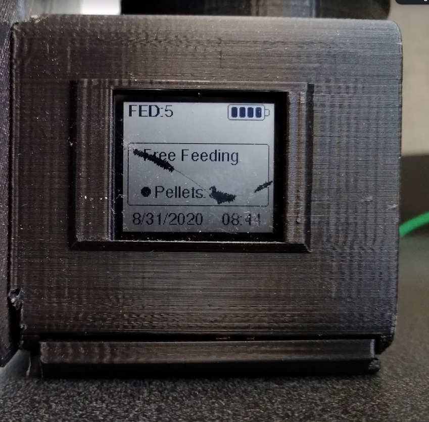
The screen is fragile and can crack if the 3D print puts pressure on it when you are putting it into the housing. While you cannot repair the screen once it is cracked, you can replace it fairly easily.
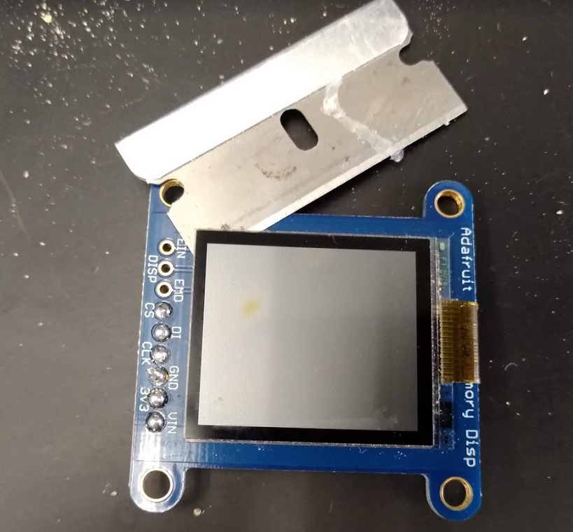
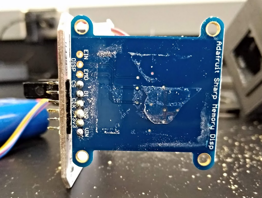
The Adafruit Sharp Memory Display module contains two parts: 1) the display itself, made by Sharp and connected by a thin ribbon cable to 2) the Breakout PCB made by Adafruit. It is easiest to leave the break-out board on the FED3 PCB in place and just replace the display. This is much easier than de-soldering the breakout board to remove it from the PCB. Unfortunately you cannot purchase the display from Sharp in quantities <1000 so you will likely need to purchase a whole new screen assembly from Adafruit to do this repair.
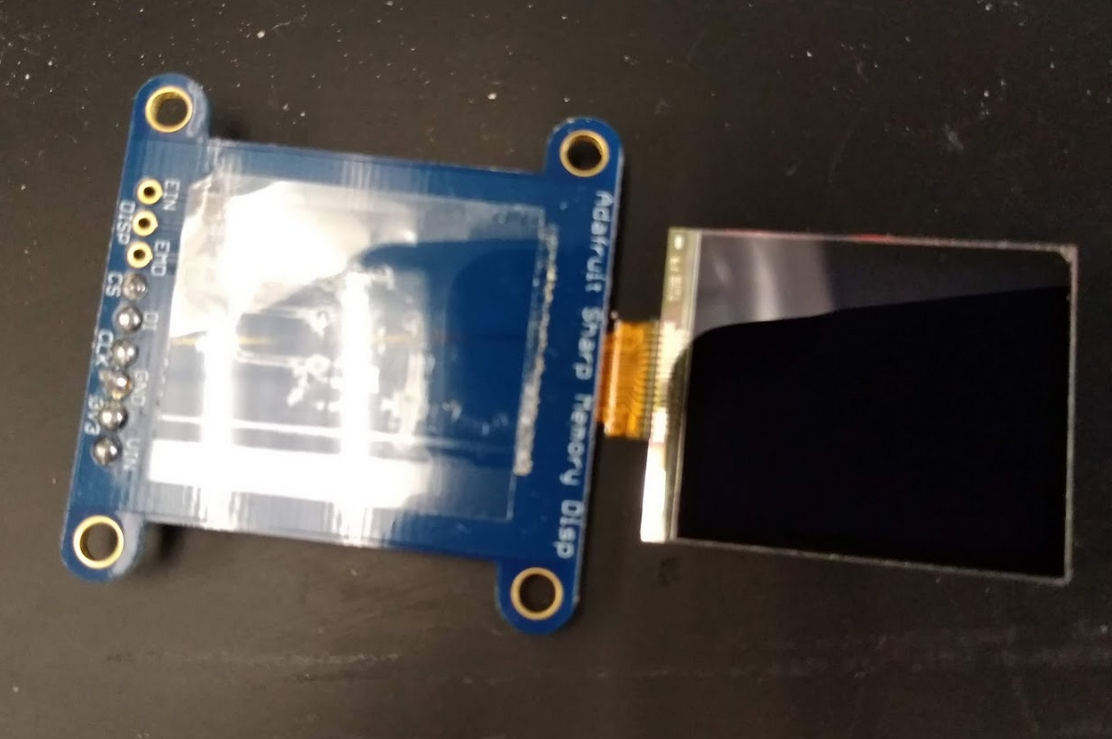
It is attached with double sided tape that can be separated with a razor blade. Separate the displays from the breakout boards for both the cracked display and the new display.
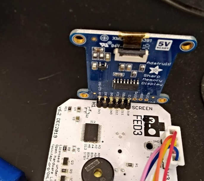
The ribbon cable is attached with a flip up quick connector (yellow arrow)
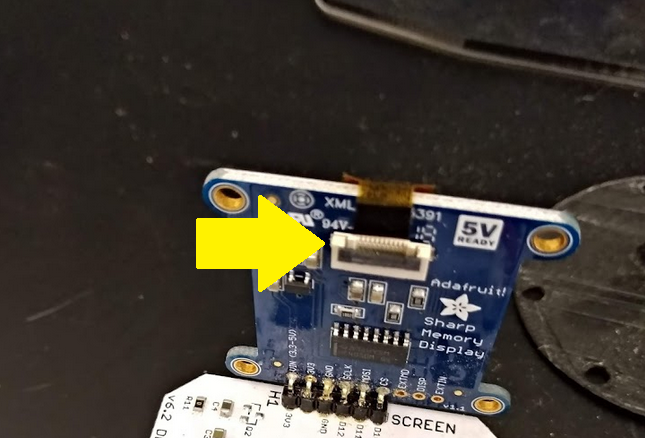
Then just reconnect the ribbon cable and put everything back together. You're done!
Removing the BNC is the most cumbersome part. I was trying to remove them altogether, but it ended up being faster if clipping the leads (I had no plans for the BNC connectors after removing from the FED).

Next, you have to remove the connector from the board. You will need a soldering iron that can get up to 430C / 800F to melt the physical anchors of the BNC.
Use solder wick to remove all the tin from the connections and forceps to pull the BNC out of the main board.

You can get different 3.5 mm female connectors. I used SJ1-3533NG from Mouser. They are bulky, which should help with mechanical stability. I soldered leads (AWG22 wires) to the contacts from (A0 to postive, ground to ground). If reusing the leads from the BNC, you can solder to those. Otherwise, you can pass the wires through the main board and solder onto the other side.
Before hot gluing, you should definitely test the signal with any program that sends signal through the serial output
It's a good idea to try mock placement beforehand to get an idea of where the connector should end. The connector should be flush enough to the board to allow the 3D printed casing to fit. I put a few drops of hot glue on the main board and glued the connector in place. I put another few drops on top to insulate the leads and add extra support. This is how it looks like with hot glue.
 .
.
Finally, this is how it looks like inside the 3D print.
