MathChallenges
The basic idea to draw thread diagrams is drawing small curved segments of lines. A shadow for each segment creates the over/under effect. A shadow with a colour identical to the background creates the traditional diagrams:
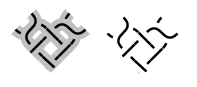
Unlike traditional diagrams, the diagram above shows no ends come out of the stitch going to the bobbins. That is a technical work-around for better chaining the stitches together. If the chaining can not be improved, such that it can deal with overlapping ends, the program should extend the loose ends for a while. This is rather a programming challenge than a mathematical challenge, though it might be tricky in what direction to extend the loose ends.
The following code snippet shows how to define the Bezier curves of a half stitch. Note that the "." is for the decimals and the "," separates X from Y. X being the horizontal distance from the left side of the canvas, and Y the vertical distance from the top side of the canvas, so 0,0 is the top left corner.
<stitch id="tc" pairs="15-16">
    <pair start="3,13.3" end="13.5,3" />
    <pair start="3,3" end="13.5,13.5" />
    <twist bobbins="1-2">
        <back start="0,6.6" end="5,11.6" />
        <front start="5,2" c1="5,5" c2="5,5" end="0,10" />
    </twist>
    <twist bobbins="3-4">
        <back start="11.6,2" c1="11.6,5" c2="11.6,5" end="16.6,10" />
        <front start="16.6,6.6" end="11.6,11.6" />
    </twist>
    <cross bobbins="2-3">
        <back start="11.6,11.6" end="6.6,16.6" />
        <front start="5,11.6" end="10,16.3" />
    </cross>
</stitch>
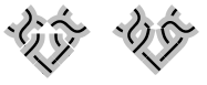
Combining two of such twists and a cross, would result in the left diagram. The right versions shows what happens when the program knows how to make the ends meet. But just making the ends meet is not sufficient. The "shadow" still shows a gap.
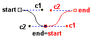
As shown in the picture above, not only the black end and red start should be on the same spot, but they should also be on a straight line with black c2 and red c1. That might be a smaller challenge than extending the ends discussed above. But it adds to the tension challenge discussed below.
In this example of a striped Vierge ground, the drunken coloured lines show that the program doesn't know how to tension the threads.
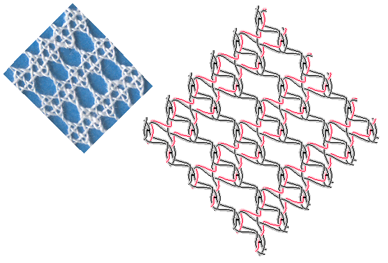
After making the segment ends meet and put the control points in a straight line as described above. Subsequently the line/thread should be flattened/tensioned. This flattening process has some restrictions:
- threads cannot move through pins
- segments within a "switch" should stay together: an X should not turn into a T or even separated, where the width of the shadow and angle determines when an X turns into a T.
On a pair level flattening lines is less an issue but when an X turns into a T is not so well defined.
Selecting threads has an obvious bug. The current strategy is drizzling into the details of the tree until the cross or twist is found that contains the mouse pointer. Then nearest thread is highlighted. The following issue show why some sections at the edge sometimes can't be selected.
(a) 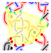 (b)
(b) 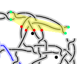
In the images above, the yellow areas are the bounding polygons of a group of stitches, used to highlight them. The coloured dots show the start points and end points of the selected group of stitches that define the polygon. That is a quick and dirty solution. It usually works when just drawing grounds. But the polygon in (a) should extend to the left and the polygon in (b) should extend at the top. Stitches chained to a moon slice would be even worse.
The green dots are the ins, the reds the outs of Connectors.java
The improved approach below adds dots between the green and red dots. That should improve (a). However we need additional points between the green dots in (b). So I'm afraid we have to store the polygon in a field, and merge them in the method connect.
The stored polygons should reflect changes made by setNext in Connectors.connect
Possible hints on:
http://valis.cs.uiuc.edu/~sariel/research/CG/applets/convex_decomp/Default.html
http://cgm.cs.mcgill.ca/~orm/mergech.html
The Connectors class looses information about internal segments.
We should also merge the bounding polygons of the children
and store the result with the parent.
Using polygons is more complex than rectangular bounding boxes, but rectangles would cause overlap.
We can't use overlap when drizzling down the tree to find which thread is pointed at.
https://raw.githubusercontent.com/wiki/d-bl/bobbinwork/master/src/nl/BobbinWork/diagram/model/Connectors.java?r=244
implements an improvement at stitch level. It tries to use control points too, but needs the following changes:
addPoint(b.getStart(), a.getEnd(),rights,b.getC1());

addPoint(b.getStart(), a.getEnd(),rights,a.getC2());

addPoint(b.getEnd(), a.getStart(),lefts,b.getC2());

addPoint(b.getEnd(), a.getStart(),lefts,a.getC1());

...

/** Adds east to list if the compas is only rotated and not mirrored. */

private void addPoint(Point north, Point south, List<Point> list, Point east){
The method addPoint would need the method isMirrored below, but how to imlement it?
import java.awt.geom.Point2D;

public class Compas {

  private static boolean isMirrored(

       Point2D north,

       Point2D east,

       Point2D south)

  {

     return false;

  }

  public static void main (String[] args) {

    Point2D[][] ps = {

      // (0,0) is north-west corner of canvas, compass may be rotated

      {new Point2D.Float(1,0),new Point2D.Float(1,2),new Point2D.Float(2,1)},//false

      {new Point2D.Float(1,1),new Point2D.Float(1,2),new Point2D.Float(0,1)},//true

    };

    for ( Point2D[] p:ps ) {

      System.out.println(isMirrored(p[0],p[1],p[2]));

    }

  }

}
Rotate east and and south together around north and return (rotatedEast.x < north.x) ?
Calculate a line through east perpendicular on north-south and do something with the direction of both lines?
Would java.awt.geom.AffineTransform and/or java.awt.Graphics2D be useful?